White Papers & Technical Briefs
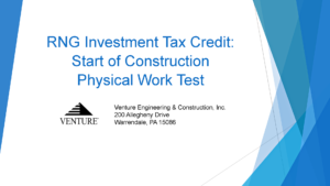
Renewable Energy/Biogas
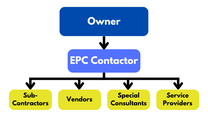
Contracting Strategies
Commissioning

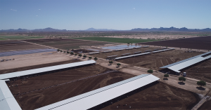
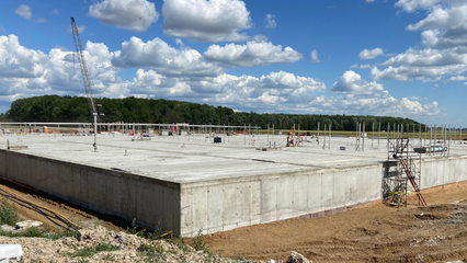
Venture recently broke ground on another Dairy Digester-to-RNG Facility located in Arizona. This dairy farm milks approximately 9,000 cows. Once complete, the facility is expected to annually reduce 33,000 metric tons of greenhouse gas emissions, while generating over 73,000 MMBtu of RNG every year.